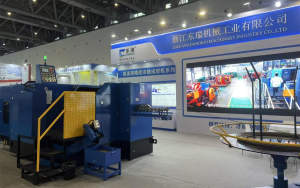
Dongrui Machinery Unveils Multi-Station Cold Heading Equipment at the 2026
 Skip to content
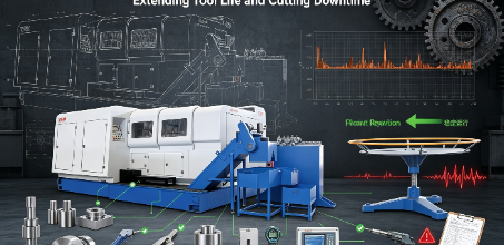
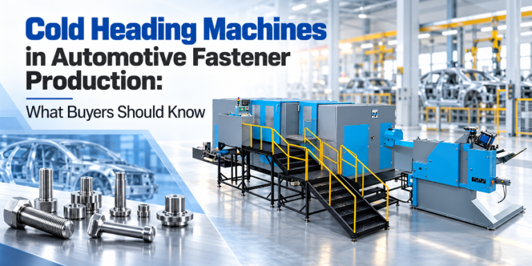
When a cold heading machine runs at 350–450 strokes per minute, each stroke drives a carbide punch into a carbide die with forces that can exceed 30–40 tons. The carbide insert — a precision-ground component made from sintered tungsten carbide with a cobalt binder — is designed to withstand this load. But its survival depends on one factor that is often invisible to the buyer at the time of purchase: the rigidity of the machine bed that supports the entire force path.
Carbide tooling is the single largest consumable cost in cold forging operations. A set of carbide dies for a 5-station M8 bolt line can cost thousands of dollars, and a high-volume fastener plant may replace die sets every few weeks. Manufacturers invest heavily in premium carbide grades, PVD coatings, and sophisticated die life tracking systems — and then mount those dies in a machine whose bed deflects under load, transmitting vibration and misalignment forces that chip, crack, and wear the carbide prematurely.
This article examines the mechanical relationship between machine bed design and carbide tooling life. We cover the force transmission path in cold forming, the material science behind cast iron’s damping superiority, how bed deflection creates stress concentrations in carbide inserts, and the practical evaluation criteria that buyers should use when assessing machine structural quality.
Table of Contents
In a high-volume cold heading operation, the cost breakdown per part looks roughly like this: raw material (wire) is the largest line item, but tooling is the second largest operating expense — and it is the one most directly influenced by machine design. Labor, energy, and floor space are relatively fixed costs; tooling cost per part is variable and can swing dramatically based on how long each die set lasts.

The reason most fastener manufacturers have already switched to tungsten carbide dies is clear: carbide lasts dramatically longer than tool steel. According to data from multiple carbide tooling suppliers, the typical lifespan comparison is:
| Die Material | Typical Lifespan | Dimensional Drift | Relative Cost per Part |
|---|---|---|---|
| Tool steel (D2, M2) | 50,000 – 200,000 cycles | Significant (0.02mm after 2 hrs) | Baseline (1.0x) |
| Tungsten carbide (WC-Co) | 1,000,000 – 5,000,000 cycles | Minimal (<0.002mm after extended runs) | 0.02x – 0.10x |
| Carbide + PVD coating (TiN/TiAlN) | 2,000,000 – 8,000,000 cycles | Excellent (±0.003mm after 1M cycles) | 0.01x – 0.05x |
The lifespan advantage of carbide — 10 to 50 times longer than tool steel — is well established. But these numbers assume ideal operating conditions: proper die alignment, consistent material feed, adequate lubrication, and — critically — a machine bed that does not deflect or vibrate under load. When the machine structure is inadequate, the real-world carbide die life can fall to 30–50% of the theoretical maximum, eroding the economic advantage that justified the carbide investment in the first place.
Every percentage point of die life lost to machine-induced stress is money directly subtracted from the operation’s margin. A die set that should last 3 million cycles but fails at 1.5 million because of bed deflection effectively doubles the tooling cost per part — and adds unplanned downtime for die changes that disrupt the production schedule.
To understand why the machine bed matters, we need to trace the force path through the cold forming machine. Every forming blow creates a complex chain of mechanical events:
When the main ram strikes, the forming force travels through this sequence:
Force Path in a Cold Heading Machine
1. Main motor energy → flywheel →
2. Crank mechanism (converts rotation to linear stroke) →
3. Ram (linear motion with punch attached) →
4. Punch strikes billet (wire slug) →
5. Bilinear material flows into die cavity →
6. Forming force transfers through die → die holder →
7. Die seat / bolster plate →
8. Machine bed (the structural foundation) →
9. Foundation / floor anchor → ground
The machine bed is the last structural element in this chain — and the one that must absorb all the reaction force from the forming blow. If the bed is rigid, the force passes cleanly through to the foundation. If the bed flexes, several destructive things happen simultaneously:
The pressures involved in cold heading are extreme. For common fastener materials and sizes, the typical forming pressures are:
| Material | Yield Strength (MPa) | Approx. Forming Pressure | Machine Force Required |
|---|---|---|---|
| Low carbon steel (1010) | ~300 | ~800–1,200 MPa | Moderate |
| Boron steel (10B21) | ~350–420 | ~1,000–1,500 MPa | High |
| Alloy steel (SCM435) | ~500–600 | ~1,500–2,000 MPa | Very high |
| Stainless steel (SS304) | ~520–700 | ~1,800–2,500 MPa | Extreme |
At these pressures, the carbide die insert is working at 20–40% of its compressive strength limit. That margin is sufficient — but only if the load is distributed evenly across the die. Any bed deflection that causes the punch to enter the die at an angle, or the die to shift in its holder, immediately creates stress concentrations that can exceed the carbide’s localized strength, causing micro-chipping or cracking.
The material and construction method of the machine bed is the single most important structural decision in cold former design. Two materials dominate the industry: cast iron and welded steel fabrication. Each has distinct properties that affect tooling life.
Gray cast iron has been the preferred material for machine tool structures for over a century, and for good reason. Its microstructure contains flake graphite dispersed throughout the iron matrix. These graphite flakes serve a dual purpose:
Research on machine tool casting materials has quantified the damping hierarchy:
Relative Damping Capacity (Higher = Better Vibration Absorption)
Gray cast iron: 1.00 (baseline — highest)
Ductile iron: ~0.50 (half of gray iron)
Low-carbon steel: ~0.20 (one-fifth of gray iron)
Welded steel fabrication: ~0.15–0.20 (comparable to steel, but joints introduce additional resonance)
In practical terms, a gray cast iron bed absorbs approximately 5 times more vibrational energy per cycle than a welded steel frame of equivalent mass. This means that the shock from each forming blow — which in a steel frame would bounce through the structure and reflect back into the die — is instead absorbed and converted to heat within the iron matrix.
Welded steel beds are sometimes used in lighter-duty cold formers or to reduce manufacturing cost and weight. Steel has higher tensile strength than cast iron, which means a steel bed can be designed to be lighter while achieving similar static stiffness. However, the key word is “static” — steel’s weakness is in dynamic performance:
The material is only part of the equation. The internal geometry of the casting — the ribbing pattern, wall thickness distribution, and mass placement — determines how effectively the bed resists deflection and manages vibration. Well-designed cast iron beds incorporate:
The connection between bed rigidity and carbide die life is not intuitive — it is mechanical. To understand it, we need to look at what happens to the carbide insert when the bed deflects, even by a few microns.
Under a forming load of 30–40 tons, even a well-designed machine bed will deflect slightly. The question is how much, and whether that deflection is within the tolerance band of the die alignment system. Consider this scenario:
Carbide dies are designed for uniform compressive loading — the force of the punch should be distributed evenly across the die bore. When the machine bed deflects, the punch enters the die at a slight angle. This creates a stress concentration at the entry edge of the die on the side where the punch first contacts. The stress at this point can be 2–3 times higher than the nominal pressure.
Tungsten carbide has exceptional compressive strength (up to 6,000 MPa) but relatively low tensile strength (1,500–2,400 MPa depending on grade). When the punch enters the die off-center, the bending moment created at the die entry edge generates tensile stress in the carbide — and this is where cracks initiate. Once a micro-crack forms, each subsequent blow propagates it further, until the die fails catastrophically.
A properly designed cast iron bed with adequate mass and ribbing keeps deflection within the die’s tolerance band. The force passes through the die holder and into the bed as a clean, axial load — no bending moment, no stress concentration. The carbide insert sees uniform compressive stress across its entire bore, which is exactly what it is designed to handle.
The Dongrui DBP-206L illustrates this principle. With a machine weight of 80 tons and a forging force of 390,000 kgf, the bed is designed with a mass-to-force ratio that ensures minimal deflection. The 6-station configuration distributes the forming load across more operations, reducing the per-station peak force — but the bed must still absorb nearly 400 tons of reaction force per stroke. The heavy cast iron construction ensures that this force is channeled cleanly to the foundation, not reflected back into the carbide tooling.
Vibration is the less obvious — but equally destructive — companion to deflection. While deflection causes static misalignment, vibration causes dynamic stress cycling that fatigues the carbide insert over thousands of blows.
Every forming blow is an impact event. When the punch strikes the billet and the metal flows into the die, the sudden deceleration of the ram generates a shock wave. This shock travels through the die, through the die holder, and into the machine bed. What happens next depends entirely on the bed material:
Every structure has a natural frequency — the frequency at which it vibrates most easily when disturbed. If the operating frequency of the cold former (the strokes-per-minute rate) happens to coincide with, or be near, the natural frequency of the machine bed, a phenomenon called resonance occurs. In resonance, the vibration amplitude increases with each successive blow rather than decaying.
Resonance is particularly dangerous because it is invisible to the operator in its early stages. The machine appears to run normally, but the internal vibration amplitude is building with each stroke. The carbide insert is subjected to cyclic stress that grows over minutes or hours, until the stress exceeds the carbide’s fatigue limit and the die fails — often without warning.
Cast iron’s superior damping capacity means that resonance is far less likely to develop. Even if the operating frequency is near the bed’s natural frequency, the high damping ratio prevents the vibration amplitude from building. The graphite flake network dissipates the energy of each cycle before the next blow arrives.
Vibration-induced die failure typically manifests as micro-chipping at the die entry edge. The mechanism is:
A well-damped cast iron bed breaks this cycle at step 1 — the vibration that would initiate the tensile stress is absorbed before it reaches the carbide.
The theoretical connection between bed rigidity and die life is clear — but what does it look like in practice? Here are the symptoms that fastener manufacturers experience when their machine bed is inadequate:
Carbide dies that should last 2–3 million cycles begin cracking at 500,000–800,000 cycles. The cracks typically originate at the die entry edge and propagate radially. This is the classic signature of vibration-induced fatigue — and it is the first sign that the machine bed is not absorbing impact energy effectively.
A die set produces parts within tolerance at the start of a production run, but dimensions gradually drift out of spec after several hours. This is not normal die wear — it is thermal deflection. As the machine warms up, the bed expands. In a steel bed, the higher thermal expansion coefficient causes greater dimensional change. In a cast iron bed, the lower expansion coefficient and greater thermal mass keep the structure dimensionally stable.
In a multi-station former, parts produced at one station may be consistently within tolerance while parts from another station drift. This often indicates that the bed is deflecting unevenly — the ribbing pattern or mass distribution is not providing uniform support across the die area. The solution is not to adjust the die (which only masks the problem) but to address the root cause: insufficient structural support at that station location.
After a die change, the machine produces high scrap rates that take longer than expected to bring under control. This indicates that the die alignment system cannot compensate for bed imperfections — the bed may have wear damage at the die seat interface, or the structure has warped over time due to inadequate stress relief.
In severe cases, the machine physically shifts on its foundation, or vibrations are felt in the floor several meters away. This is a sign of grossly insufficient mass or damping — the machine is acting as a vibration source rather than a vibration absorber. Not only does this destroy tooling life, but it can also damage nearby equipment and create an unsafe working environment.
When comparing cold forming machines — whether at a factory visit, trade show, or from a specification sheet — the machine bed is the component most worth scrutinizing. Here is a practical buyer’s checklist:
Dongrui Machine Bed Specifications
| Parameter | DBP-136L | DBP-206L |
|---|---|---|
| Machine weight | 35 tons | 80 tons |
| Forging force | 140,000 kgf (140T) | 390,000 kgf (390T) |
| Mass/Force ratio | 0.25 tons/ton | 0.21 tons/ton |
| Bed material | Heavy cast iron | Heavy cast iron |
| Footprint (mm) | 10,500 × 4,000 | 14,500 × 6,000 |
Both models exceed the 0.15–0.20 tons/ton mass-to-force ratio threshold, indicating substantial structural mass relative to forming capacity.
Machine bed rigidity can affect carbide die life by 30–50% or more. Carbide dies are designed for uniform compressive loading, but a bed that deflects under forming force causes the punch to enter the die off-center, creating stress concentrations at the die entry edge. In machines with inadequate bed rigidity, carbide dies that should last 2–3 million cycles may fail at 1–1.5 million — effectively doubling tooling cost per part. The effect is most pronounced with harder materials (alloy steels, stainless steel) and higher-speed operations, where impact forces are greater and vibration fatigue is more aggressive. Contact Dongrui’s engineers to discuss die life optimization for your specific application.
The primary difference is vibration damping capacity. Gray cast iron contains graphite flakes that act as internal friction points, dissipating vibrational energy as heat. Gray cast iron has approximately 5 times the damping capacity of low-carbon steel. Welded steel beds transmit vibration with minimal absorption, causing shock waves to reflect back into the carbide tooling. Steel is stronger in tension and can be lighter for equivalent static stiffness, but its poor dynamic performance — higher vibration transmission, thermal expansion, and weld-joint resonance — makes it less suitable for high-speed cold forming. Cast iron also offers better thermal stability (lower expansion coefficient) and natural lubricity at guide surfaces, both of which contribute to long-term dimensional accuracy and die life.
Yes — vibration is one of the most common and least recognized causes of premature carbide die failure. Each forming blow generates a shock wave. In a machine with poor vibration damping (such as a welded steel bed), this shock reflects back into the carbide insert as a tensile stress pulse. While tungsten carbide has exceptional compressive strength (up to 6,000 MPa), its tensile strength is much lower (1,500–2,400 MPa). Repeated tensile stress cycling — at 350–450 cycles per minute — causes fatigue crack initiation at the die entry edge, followed by micro-chipping and eventual die failure. This mechanism, called vibration-induced fatigue, can reduce die life by 30–50% compared to the same die running in a properly damped machine. The solution is a cast iron bed with adequate mass and ribbing that absorbs the shock before it reaches the carbide.
Use this checklist: (1) Confirm the bed material — it should be cast iron (gray or ductile), not welded steel. Ask for the material specification. (2) Check the mass-to-force ratio — divide machine weight (tons) by forging force (tons). A ratio below 0.15 suggests an undersized bed. (3) Ask about stress relief — the bed should have been aged or thermally stress-relieved before final machining. (4) Listen to the machine run — a well-damped machine produces a muffled, solid sound. Sharp, ringing sounds indicate poor damping. (5) Feel the floor — if vibration is perceptible more than 2–3 meters from the machine, the bed is not absorbing impact effectively. (6) Ask for die life data — a manufacturer confident in their bed design should provide typical carbide die life numbers from existing customers.
Under proper conditions — a rigid cast iron machine bed, adequate lubrication, correct die alignment, and appropriate material feed — a tungsten carbide die in cold heading service typically lasts 1–5 million cycles before requiring replacement or refurbishment. With PVD coatings (TiN, TiAlN), this can extend to 2–8 million cycles. However, these numbers are achievable only when the machine structure provides the necessary rigidity and damping. In machines with inadequate beds, real-world die life may fall to 30–50% of these figures. Carbide dies can also be refurbished — typically reground to a slightly smaller bore diameter and re-coated — extending total die set life by 2–3 refurbishment cycles. The DBP-136L and DBP-206L are engineered with heavy cast iron beds to maximize carbide die life.
Carbide tooling life is not determined by the carbide alone. The machine bed is the structural foundation that determines whether the carbide insert sees clean, uniform compressive loading — or destructive tensile stress from deflection and vibration. The economic logic is straightforward:
When evaluating cold forming machines, the bed is the one component that cannot be upgraded or retrofitted later. You can change tooling, add coatings, upgrade controls, and improve material feed — but if the machine bed is inadequate, you will spend the life of the equipment paying for it in shortened die life, increased scrap, and unplanned downtime. Choose a machine with a heavy cast iron bed, adequate mass-to-force ratio, and verified stress relief — and your carbide tooling investment will deliver its full theoretical return.
Dongrui’s cold forming machines are built on heavy cast iron beds engineered for maximum rigidity and vibration dampening. The DBP-136L (35 tons, 140T forging force, for 8–12mm parts) and the DBP-206L (80 tons, 390T forging force, for 12–20mm parts) are designed to protect your carbide tooling investment through structural rigidity that cannot be matched by lighter, welded-steel alternatives. As a National High-Tech Enterprise with exports to 145+ countries, Dongrui provides the engineering depth and manufacturing quality that fastener producers demand.
Maximize Your Carbide Tooling Life
Tell us your part size, material, and production volume. Our engineers will recommend the machine configuration with the optimal bed rigidity for your tooling investment.
Dongrui Equipment (Zhejiang DongRui Machinery Industry Co., Ltd.) is a National High-Tech Enterprise specializing in cold heading machines and multi-station cold formers. Products are exported to 145+ countries including India, Turkey, Russia, Brazil, and Southeast Asia. Visit our website for product specifications and quotations.
Dongrui Machinery Unveils Multi-Station Cold Heading Equipment at the 2026
1. Introduction For decades, “Made in China” in the machinery
Table of Contents Introduction Material utilization: cold forming achieves 90–95%
1. Introduction In the highly competitive arena of high-volume industrial
 Optimized by Seraphinite Accelerator