Table of Contents Introduction What smart cold forming actually means
 Skip to content
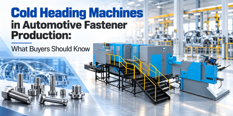
Walk into any fastener manufacturing facility and you will see rows of cold heading machines — but they are not all the same. Some are dedicated bolt formers, designed to produce externally threaded fasteners with long shanks and formed heads. Others are nut formers, engineered specifically for the unique geometry of internally threaded fasteners with through-holes. And increasingly, many are multi-purpose part formers — flexible machines that can handle bolts, nuts, and non-standard custom parts on the same platform.
Understanding the design differences between these machine types is essential for making the right equipment investment. A bolt former pressed into nut production will struggle with the piercing operation and lack the transfer mechanism needed to flip parts between stations. A dedicated nut former, while efficient for high-volume standard nut production, cannot produce the long shanks and complex head geometries required for specialized bolts. And for manufacturers producing custom or non-standard parts, neither dedicated machine may be the right choice.
This guide examines the fundamental design differences between nut formers, bolt formers, and multi-purpose part formers — covering extrusion type, punch and die arrangement, transfer mechanisms, tooling considerations, and the practical decision of when to choose a dedicated machine versus a flexible part former. Whether you are setting up a new fastener production line or expanding your existing capacity, understanding these distinctions will help you select the machine that matches your product range and production strategy.
Table of Contents
The distinction between bolt formers and nut formers begins with the fundamental metal-forming process each employs. Cold heading relies on two primary deformation categories — upsetting (compressing material to increase diameter) and extrusion (forcing material through a restricted opening to change its shape). The direction of extrusion is what separates bolt forming from nut forming at the most basic level.

Bolts are “long and thin” parts. The forming process uses forward extrusion — the metal flows in the same direction as the punch movement, passing through a smaller die opening to reduce the shank diameter and extend the part length. This is how a bolt’s reduced shank is formed: the wire enters the die at its original diameter, and the punch pushes it forward through a narrower section, elongating it while reducing the cross-section.
Simultaneously, upsetting is used to form the bolt head. Material at the end of the wire is compressed into a die cavity, expanding radially to form the hex, flange, or socket head shape. The combination of forward extrusion (for the shank) and upsetting (for the head) defines the bolt forming process.
Nuts are “short and stout” parts with a critical feature that bolts do not have: a through-hole. This hole is created through backward extrusion — a fundamentally different process where the metal flows in the opposite direction of the punch movement. A piercing pin is driven into the material confined inside the die, and the metal flows backward (upward) around the pin, creating a hollow cavity.
For standard nuts, this process occurs progressively. In the early stations, the blank is upset to form the basic hexagonal or round shape. In intermediate stations, backward extrusion begins creating the hole from one side. In the final station, a piercing operation shears through a thin web of material remaining between the two partially formed holes, creating a clean through-hole. This piercing step is unique to nut forming and requires specialized tooling — a hardened piercing pin and a corresponding die with clearance for the slug to exit.
| Characteristic | Bolt Former | Nut Former |
|---|---|---|
| Primary extrusion type | Forward extrusion (metal flows with punch) | Backward extrusion (metal flows against punch) |
| Part geometry | Long and thin (length > diameter) | Short and stout (height ≤ diameter) |
| Through-hole operation | Not applicable | Piercing — shears web between two partially formed holes |
| Threading method | Thread rolling (external — flat or planetary dies) | Tapping (internal — cut or form tap) |
| Typical stroke length | Long stroke (accommodates full shank length) | Short stroke (part height is small) |
A bolt former is designed around the progressive forming of an externally threaded fastener. The punch and die arrangement at each station performs a specific operation in sequence, gradually transforming a cylindrical wire blank into a finished bolt with a formed head, reduced or full-diameter shank, and prepared thread section.
A standard 4-station bolt former, such as Dongrui’s DBF-134L, performs the following operations:
The key characteristic of this arrangement is that the part maintains its orientation throughout the process — the head end is always presented to the punch, and the shank extends through the die. This allows a simple, efficient linear transfer mechanism.
A nut former follows a fundamentally different forming sequence. Because the nut has a through-hole that must be formed from both sides, the part must be flipped between stations — allowing punches to work on alternating faces. This requirement drives the unique design of the nut former’s tooling and transfer system.
A standard multi-station nut former performs the following progressive operations:
This sequence reveals why a bolt former cannot efficiently produce nuts: the part flip at Station 4 requires a transfer mechanism designed for rotation, and the piercing operation at Station 5 requires a hardened piercing pin and slug clearance that bolt formers do not have. Attempting nut production on a bolt former would require extensive modification and would still lack the optimized short-stroke, high-speed design of a dedicated nut former.
Why the Piercing Operation Matters
The piercing step is the defining operation of nut forming. Unlike forward extrusion (which simply reshapes material), piercing removes a small slug of material to create the through-hole. This slug — typically 5–10% of the blank’s total volume — is the only material waste in the cold heading process. The piercing pin must be made from high-wear-resistant carbide, as it experiences extreme compressive stress and abrasion with every cycle. Pin wear is one of the most common maintenance items on nut formers.
The transfer mechanism — the system that moves the part from one station to the next — is one of the most significant design differences between bolt formers and nut formers. This difference is driven by the fundamental geometry of the parts being produced.
Bolts are elongated parts that maintain the same orientation throughout the forming process. The head is always at the punch side, and the shank extends through the die. This allows bolt formers to use a linear finger transfer — a set of cam-driven fingers that grip the shank of the part, extract it from one die, move it horizontally to the next die, and insert it. The part is never rotated or flipped.
This linear transfer is fast, reliable, and well-suited to long-stroke machines. The transfer fingers are designed to grip cylindrical or reduced-diameter shanks, and the finger shape is relatively simple — typically a V-groove or matching profile that centers the part axially.
Nuts require a fundamentally different transfer approach. Because backward extrusion must be performed from both sides of the part, the nut must be flipped 180° between specific stations. This requires a transfer mechanism that can:
This flip transfer mechanism is more complex than linear finger transfer. It typically uses an open-close clamp system driven by an S-plate or cam mechanism that grips the nut blank, rotates it, and places it in the next die. The added complexity means nut former transfer systems require more maintenance and are more sensitive to part size variations during changeover.
| Feature | Bolt Former Transfer | Nut Former Transfer |
|---|---|---|
| Motion type | Linear (horizontal extraction and insertion) | Linear + 180° rotation at specific stations |
| Finger geometry | V-groove, grips cylindrical shank | Clamp/gripper, grips hex or round block |
| Knockout stroke | Long (must clear full shank length) | Short (part height is small) |
| Complexity | Lower — simple cam-driven fingers | Higher — flip mechanism, ejector, orientation control |
| Changeover effort | Moderate — replace fingers, adjust feed | Higher — replace grippers, adjust flip timing, set piercing pin |
The choice between a dedicated nut former and a multi-purpose part former comes down to your production strategy. If you are manufacturing millions of standard hex nuts per month, a dedicated nut former optimized for that specific part will deliver the highest speed and lowest per-piece cost. But if your production involves a mix of part types — bolts, nuts, and custom components — a part former offers flexibility that dedicated machines cannot match.
Dongrui Part Former Specifications
| Specification | DBP-136L | DBP-206L |
|---|---|---|
| Stations | 6 | 6 |
| Diameter range | 8–12.7 mm | 12–20 mm |
| Max part length | 160 mm | 220 mm |
| Forging force | 140,000 kgf | 390,000 kgf |
| Output rate | 60–90 pcs/min | 40–70 pcs/min |
| Main motor | 45 kW | 90 kW |
| Die pitch | 110 mm | 140 mm |
| Approx. weight | 35 tons | 80 tons |
| Part types | Standard & non-standard bolts, nuts, custom parts | Large standard & non-standard bolts, nuts, custom parts |
Both machines feature 6-station configurations with sufficient forging force to handle alloy steels and challenging geometries. DBP-136L product page · DBP-206L product page
The most compelling case for a multi-purpose part former emerges when the product range includes non-standard or custom-engineered parts — components that do not fit neatly into the “bolt” or “nut” category. These parts may include:
A 6-station part former like the DBP-136L or DBP-206L addresses these challenges by distributing deformation across more stations. Each station performs a specific, smaller deformation — reducing per-station stress, preventing material defects (cold shuts, head cracks), and enabling geometries that would be impossible on a 3- or 4-station dedicated machine.
Consider a custom component that requires: (1) initial upsetting, (2) forward extrusion to reduce shank diameter, (3) a second forward extrusion for a further diameter reduction, (4) backward extrusion to create a blind cavity, (5) final heading of a flange head, and (6) trimming. This six-operation sequence maps directly onto the six stations of a part former — each station performing one operation, with the part progressing linearly (with optional flip at specific stations if backward extrusion from both sides is needed).
A dedicated bolt former with 4 stations cannot accommodate this sequence — it lacks sufficient stations for both extrusion operations and the backward extrusion step. A dedicated nut former, while capable of backward extrusion, lacks the long-stroke design needed for the forward extrusion and the linear transfer for elongated parts. Only a 6-station part former can handle the full range of operations required.
Non-standard parts are often produced from more challenging materials — alloy steels (42CrMo, SCM435), stainless steel (SS304, SS316), or specialized boron steels for high-strength applications. These materials have higher flow stress and work-hardening rates, requiring greater forging force per station. The DBP-136L’s 140,000 kgf and the DBP-206L’s 390,000 kgf forging forces provide the necessary power for these materials, while the 6-station configuration distributes the total deformation to keep per-station stress within tool-safe limits.
The tooling design for bolt formers, nut formers, and part formers reflects the different forming operations each performs. Understanding these differences helps in specifying the right tooling materials, coatings, and maintenance strategies.
The knockout pin — which ejects the finished part from the die — is designed differently for each machine type:
| Tooling Component | Recommended Material | Coating Option | Primary Wear Mode |
|---|---|---|---|
| Extrusion dies | Tungsten carbide (WC-Co) | TiN or TiAlN PVD | Abrasive wear in sizing land |
| Heading punches | D2 tool steel or carbide-tipped | TiN | Compressive fatigue, surface galling |
| Piercing pins (nut forming) | Tungsten carbide | CrN or DLC | Abrasive wear, compressive fracture |
| Knockout pins | M2 or H13 tool steel | None (surface hardened) | Bending fatigue, tip wear |
Technically, a bolt former can produce simple nut-like parts — but it is inefficient and often impractical for production-scale nut manufacturing. A bolt former lacks two critical features that nut production requires: (1) a flip transfer mechanism to rotate the part 180° between stations so backward extrusion can be performed from both sides, and (2) a piercing pin and slug clearance for creating the through-hole. Without the flip mechanism, only one-sided backward extrusion is possible, resulting in a blind hole rather than a through-hole. The part would need a secondary drilling or piercing operation off the machine, eliminating the speed advantage of cold heading. For any production volume above prototype quantities, a dedicated nut former or a multi-purpose part former is the correct choice.
The threshold depends on part complexity, material, and the facility’s overall product mix. As a general guideline, if monthly production of a single standard nut type exceeds approximately 500,000 pieces, a dedicated nut former becomes economically justified — the higher speed of a dedicated short-stroke machine (typically 95+ pcs/min for small nuts) and reduced changeover overhead offset the capital investment. Below this volume, a multi-purpose part former is typically more cost-effective because it can be reconfigured for other part types when nut production is not running. For non-standard or custom nuts with complex geometries, a 6-station part former like the DBP-206L is preferable regardless of volume, because the dedicated nut former’s fixed station sequence cannot accommodate the custom forming operations required.
A 6-station part former handles non-standard geometries through distributed deformation — spreading the total forming work across more stations, with each station performing a smaller, more controlled operation. For example, a custom part requiring multi-diameter extrusion, backward extrusion for a cavity, and a complex head form can be sequenced across six stations: Station 1 for initial upset, Stations 2–3 for progressive forward extrusion, Station 4 for backward extrusion, Station 5 for final heading, and Station 6 for trimming. The key advantage is that no single station is asked to perform more deformation than the material can safely accommodate — reducing the risk of cold shuts, head cracks, and tool fracture. Custom tooling (dies, punches, knockout pins) is designed specifically for each part geometry, and the station configuration can be adjusted during changeover when switching to a different part type.
Nut formers typically run at higher strokes per minute than bolt formers of equivalent diameter capacity, because nut geometry requires a shorter stroke — the part height is much smaller than a bolt’s shank length, so the ram travel per cycle is shorter and the cycle time is faster. For example, a nut former producing M10 hex nuts might run at 90–120 pcs/min, while a bolt former producing M10 bolts runs at 75–110 pcs/min (as on the DBF-134L). However, actual production speed depends heavily on part geometry, material, and machine configuration — a complex nut with locking features may run slower than a simple bolt. Multi-purpose part formers like the DBP-136L (60–90 pcs/min) and DBP-206L (40–70 pcs/min) operate at speeds optimized for their larger diameter range and heavier forging force, prioritizing forming capability over raw speed.
Yes — a multi-purpose part former is specifically designed to produce both bolt-type and nut-type parts, along with non-standard custom components. The 6-station configuration provides enough forming stations to accommodate the full range of operations needed for both part types: forward extrusion for bolt shanks, backward extrusion and piercing for nut holes, upsetting for heads, and trimming for final sizing. When switching from bolt production to nut production (or vice versa), the tooling at each station is replaced, and the transfer mechanism is reconfigured. The changeover time is longer than on a dedicated machine — typically 2–4 hours depending on part complexity — but the flexibility of producing multiple part types on one machine eliminates the capital cost of purchasing separate bolt formers and nut formers. For facilities with a diverse product mix, this is often the most cost-effective solution.
The choice between a nut former, bolt former, and multi-purpose part former comes down to understanding your production strategy and product range:
Dongrui’s part former lineup — the DBP-136L (6-station, 140T, M8–M12, 60–90 pcs/min) and the DBP-206L (6-station, 390T, M12–M20, 40–70 pcs/min) — provides the forming force, station count, and tooling flexibility needed for mixed production of standard and non-standard parts. Whether you are producing bolts, nuts, or custom-engineered components, these machines deliver the versatility that dedicated bolt formers and nut formers cannot match.
Contact our engineering team to discuss your specific part range, production volumes, and material requirements — we will help you determine whether a dedicated machine or a multi-purpose part former is the right investment for your facility.
Need a Machine That Handles Bolts, Nuts, and Custom Parts?
Share your part drawings, material specifications, and production volumes. Our engineers will evaluate whether a dedicated former or a multi-purpose part former is the optimal configuration for your product range.
Dongrui Equipment (Zhejiang DongRui Machinery Industry Co., Ltd.) manufactures multi-station cold heading machines configurable from 3 to 8 stations, including dedicated bolt formers and multi-purpose part formers for standard and non-standard fastener production. Visit our website for full product specifications and quotations.
Table of Contents Introduction What smart cold forming actually means

Table of Contents Introduction What a cold heading machine is

Recently, Zhejiang Dongrui Machinery Industry Co., Ltd. (hereinafter referred to
Table of Contents Introduction Die anatomy Material selection between carbide
 Optimized by Seraphinite Accelerator