Wind turbines need large, fatigue-resistant bolts. See why 8-station+ high-tonnage
 Skip to content


Necking and cracking are the silent profit killers of cold heading. A single crack in a high-volume fastener line can turn a profitable shift into a scrap audit, and necking — the localized thinning that often precedes fracture — is usually mistaken for “normal” variation until rejects spike. In this guide, we explain why these defects form, how to diagnose them on the shop floor, and which process, tooling, and machine settings remove them at the source.
Table of Contents
Key Takeaways
Cold heading is prized for speed and material yield, but it leaves very little margin for error. A necked section means the shank diameter is below print; a crack means the part is scrap. When both defects appear together on the same production run, they usually trace back to one of three places: the incoming wire, the die/punch stack-up, or the machine setup.
The financial damage is bigger than the scrap bin. Cracked automotive or construction fasteners that escape detection create field-failure risk, recalls, and warranty claims. Necked sections may pass final inspection only to fail in torque-tension testing or salt-spray assemblies. Add unplanned tool changes, rework sorting, and lost machine capacity, and a “minor” defect can cost a mid-size plant tens of thousands of dollars per month.
Prevention is therefore cheaper than detection. Modern multi-station cold heading machines distribute deformation across several blows, which reduces the per-station reduction ratio and lowers the risk of necking compared with older single-blow headers. The same principle applies to 4-, 5-, and 6-station formers: spreading the work keeps local stress below the cracking threshold.
Before you tune tooling, you must name the defect correctly. Each failure mode points to a different root cause.
| Defect | What it looks like | Where it forms | Typical root cause |
|---|---|---|---|
| Necking | Visible waisting or diameter reduction below spec | Shank or transition radius | Excessive tensile stress from too-large reduction, poor die alignment, or material with low ductility |
| Micro-crack | Fine surface line, often only visible under magnification | Head-to-shank fillet or upset region | Die radius too sharp, insufficient lubrication, or shear from off-center punch |
| Shear fracture | Angular, clean break at 45° | Head upset or extruded section | Shear stress exceeds shear strength; common with high-speed overload or cold wire |
| Corner cracking | Cracks at head corners or hex points | Peripheral head edges | High friction, insufficient die radius, or excessive forming speed |
| Center burst | Internal cavity or crack along the axis | Inside the head or shank | Very high reduction, triaxial tensile stress, poor material cleanliness |
Use a 10× loupe or stereo microscope for first-line inspection. For micro-cracks and subsurface defects, dye penetrant or eddy-current testing is faster than cutting samples. Always check the defect orientation: axial cracks suggest tensile overload, while circumferential cracks around the shank often point to die clearance or lubrication issues.
Document every defect with part number, station, tool set, shift, and wire heat lot. Patterns will emerge quickly — for example, a defect that appears only on third shift may be a setup consistency problem, not a tooling problem.
The reduction ratio (also called upset ratio) compares the deformed height to the original blank height. In cold heading, higher ratios generate more deformation — and more tensile stress at the outer fibers. If the ratio exceeds the material’s formability limit, the outer surface cracks or necks.
A conservative rule of thumb for common low-carbon and medium-carbon steels is to keep the upset ratio below 2.0–2.5 per blow. For alloy steels and case-hardening grades, the safe limit is closer to 1.5–2.0. When you must form a large head in fewer blows, the risk of cracking rises; this is exactly where multi-station formers earn their keep by splitting one aggressive upset into several smaller, safer reductions.
| Material family | Safe upset ratio per blow | Notes |
|---|---|---|
| Low-carbon steel (AISI 1008–1022) | 2.0–2.5 | High ductility; most forgiving |
| Medium-carbon steel (AISI 1035–1045) | 1.8–2.2 | Watch for corner cracking if heading speed is too high |
| Alloy steel (10B21, 4140, boron) | 1.5–2.0 | Requires slower forming and higher-quality coatings |
| Stainless steel (A2, A4) | 1.3–1.7 | Work-hardens rapidly; frequent intermediate anneals may be needed |
Even with perfect tooling, inconsistent wire will create intermittent cracking. Common material problems include:
Lock in a wire specification sheet that lists diameter tolerance, tensile strength range, coating weight, and inclusion rating. Then inspect each incoming coil against that spec before it goes to the header. The cost of rejecting bad wire is tiny compared with the cost of sorting 50,000 bad parts.
For fasteners that must meet strict automotive standards, follow our guide to cold heading machines in automotive fastener production to match material grade with machine capability.
Die clearance controls how the blank flows during upsetting. Too little clearance traps the blank, raises forming load, and causes shear cracks. Too much clearance lets the blank fold or buckle, producing necked sections and off-center heads.
For most carbon-steel fasteners, start with 0.5–1.0% of blank diameter per side for finish stations and 1.0–2.0% for roughing stations. Increase clearance slightly for stainless and coated wire because they spring back more. Record the clearance that works for each part number and do not let operators “eyeball” shim changes without updating the setup sheet.
Punch angle shapes how material spreads in the die cavity. A flat punch creates more end compression but also higher lateral tensile stress at the head periphery. A conical or radiused punch reduces that tensile stress and helps material flow into corners, which is why conical punches are preferred for large-head bolts and hex heads.
Die radius at the cavity entrance is equally important. A sharp radius acts as a stress concentrator and invites corner cracking. Increasing the entrance radius by even 0.2 mm can reduce surface cracking without changing other dimensions. The trade-off is a slightly larger flash or transition zone, so radius changes must stay within print tolerances.
| Parameter | Starting recommendation | What to watch |
|---|---|---|
| Die clearance (finish) | 0.5–1.0% of blank diameter per side | Buckling / off-center head → increase; flash / galling → decrease |
| Die clearance (rough) | 1.0–2.0% per side | Cracking → decrease; uneven fill → increase |
| Punch angle | 3–7° included for upset heads; 10–15° for extrusion | Corner cracking → increase angle; head height short → decrease angle |
| Die entrance radius | 0.5–1.5 mm depending on shank diameter | Fillet cracks → increase radius; flash → decrease radius |
| Heading speed | Use the lowest speed that meets cycle target | Higher speed raises temperature and shear stress; lower for alloy grades |
For a deeper look at die materials, coatings, and reconditioning schedules, see our article on cold heading die design and maintenance.

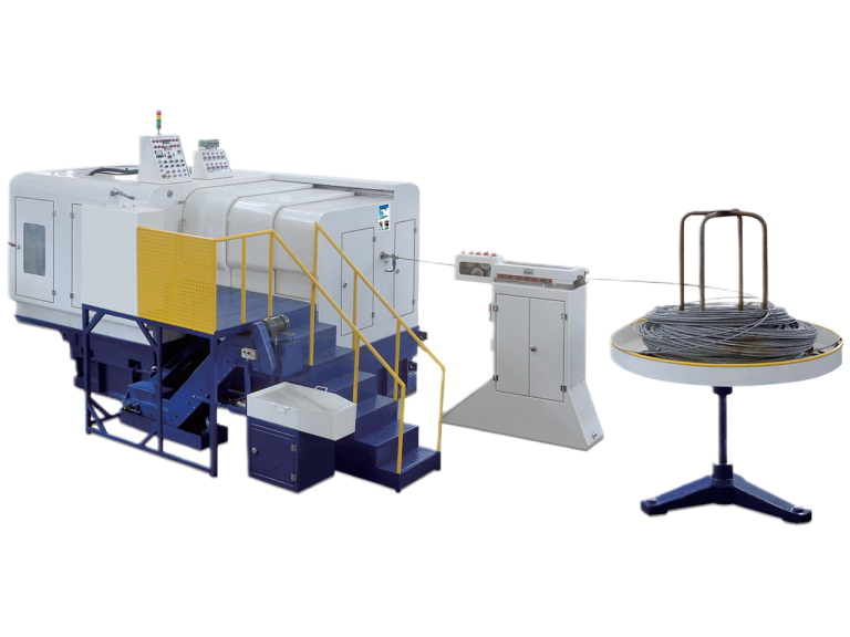
DongRui DBP-106S parts forming machine — built for stable multi-station forming with rigid bed and precision tooling alignment.
By the time an operator sees a crack, the process has usually been drifting for hundreds of parts. Sensor-based monitoring closes that gap. Modern cold formers can be fitted with:
The most useful signal is often the forming-load trend. A gradual increase indicates die wear or coating buildup; a sudden step change points to a broken insert, shifted shim, or bad wire coil. Set control limits at ±5–8% of the baseline load, and route any out-of-limit event to both the operator screen and the quality log.
We cover the full architecture in our guide to smart cold forming with IoT sensors and predictive maintenance. Machine rigidity also matters: a flexing bed changes die alignment mid-cycle and produces intermittent necking. Our article on machine bed rigidity and tooling life explains how frame design affects defect rates.
Firefighting is expensive because every response is a guess. A simple decision tree turns defect correction into a repeatable procedure.
Use the table in Section 2 to classify necking, micro-crack, shear fracture, corner crack, or center burst. Take a photo and mark the station where it first appears.
Change only one parameter per trial — clearance, punch angle, radius, speed, or wire lot — and run a controlled sample of 200–500 parts before judging the result. Record the outcome in the part history file.
Compare forming load, temperature, and vision data before and after the change. If the defect disappears but the load rises above the control limit, the fix may accelerate tool wear; look for a better balance.
| Symptom | First action | If that fails |
|---|---|---|
| Necking below head | Reduce reduction ratio or add a pre-form station | Check die alignment and bed rigidity |
| Corner cracking | Increase die entrance radius and check lubrication | Reduce heading speed or switch coating |
| Shear fracture | Lower heading speed and verify wire strength | Reduce clearance or change punch angle |
| Center burst | Reduce total upset ratio across all stations | Inspect wire cleanliness / inclusions |
| Intermittent cracks | Check coil-to-coil wire consistency | Add in-line load monitoring |
For daily and preventive maintenance tasks that keep these variables stable, use our printable cold heading machine maintenance checklist. If defects persist, the troubleshooting steps in cold heading machine maintenance and troubleshooting will help narrow the root cause.

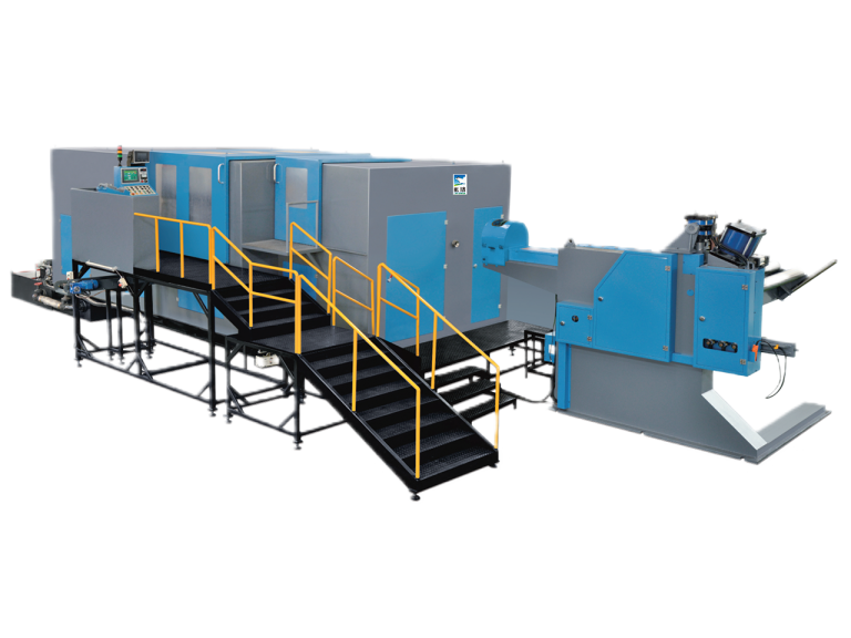
DongRui DBP-136LL multi-station cold heading machine spreads deformation across stations, cutting per-blow stress and reducing necking risk.
Necking and cracking are not random defects — they are signals that a process limit has been crossed. The most reliable fix is to reduce local stress by controlling reduction ratios, matching die clearance and punch geometry to the material, and keeping tooling aligned. Add sensor monitoring and a documented troubleshooting framework, and you move from sorting scrap to preventing it.
DongRui cold formers are engineered with rigid beds, multi-station flexibility, and sensor-ready controls to help fastener plants hold tight tolerances shift after shift. Whether you are heading standard carbon bolts or precision automotive fasteners, the right machine setup keeps necking and cracking out of your process.
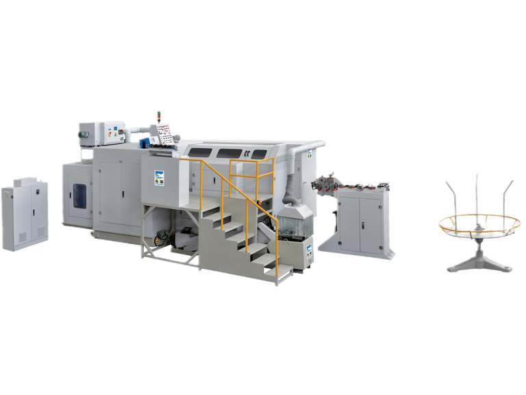
Explore the DongRui DBP-205L 5-Station Cold Former
Related reading:
Increase the die entrance radius, use a conical or radiused punch, improve lubrication, and reduce heading speed. For alloy steels, also verify that the wire coating provides enough boundary lubrication during high-pressure deformation.
Spread the total reduction so no single station exceeds the material’s safe upset ratio. Start with the largest reductions in early stations and smaller finishing reductions in later stations. If necking appears, add a pre-form or transfer station rather than forcing more deformation into one blow.
Inspect dies every 50,000–200,000 parts depending on part hardness and forming severity. Measure die clearance, entrance radius, and surface finish. Re-coat or recondition carbide dies before wear changes part dimensions. Keep a die history log so maintenance intervals can be adjusted based on actual wear rates, not calendar guesses.
Wind turbines need large, fatigue-resistant bolts. See why 8-station+ high-tonnage

1. Introduction If you are planning to set up or

Recently, Zhejiang Dongrui Machinery Industry Co., Ltd. (hereinafter referred to
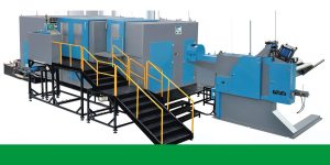
Table of Contents Introduction What thread rolling is What thread
 Optimized by Seraphinite Accelerator